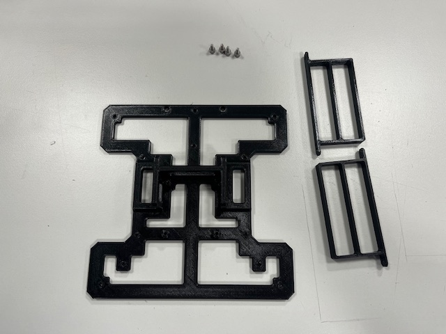
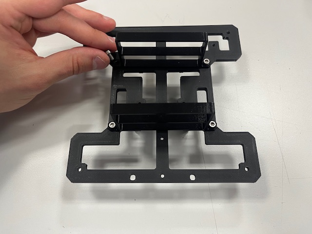
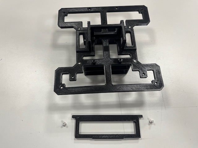
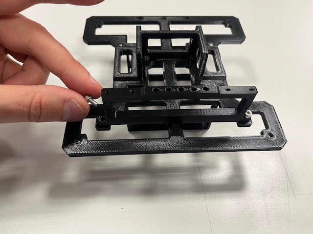
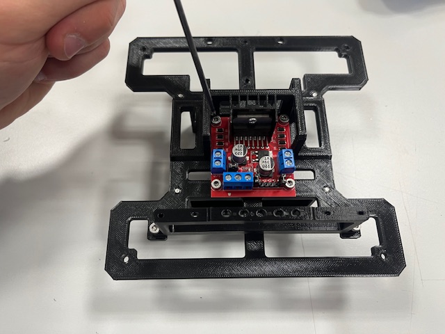
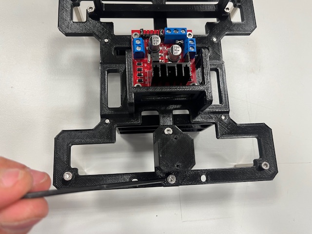
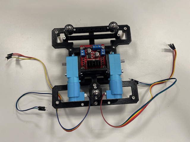
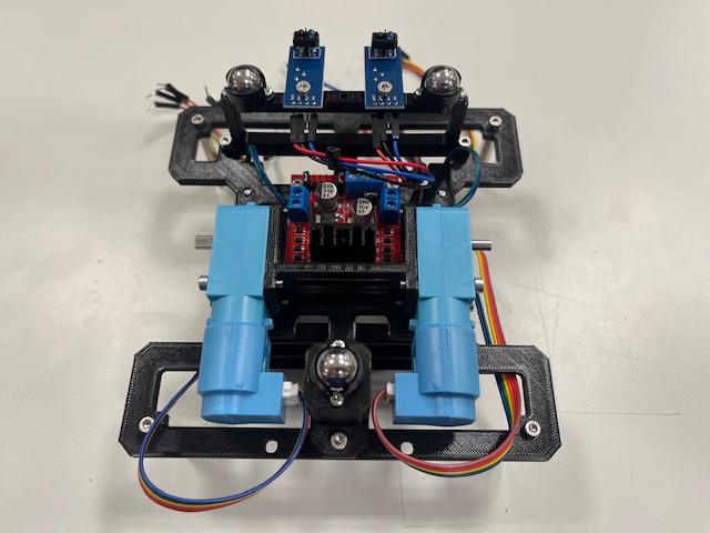
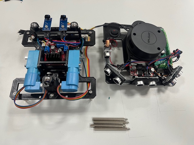
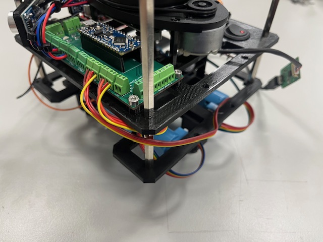
- Bottom part
- Battery holders (2x)
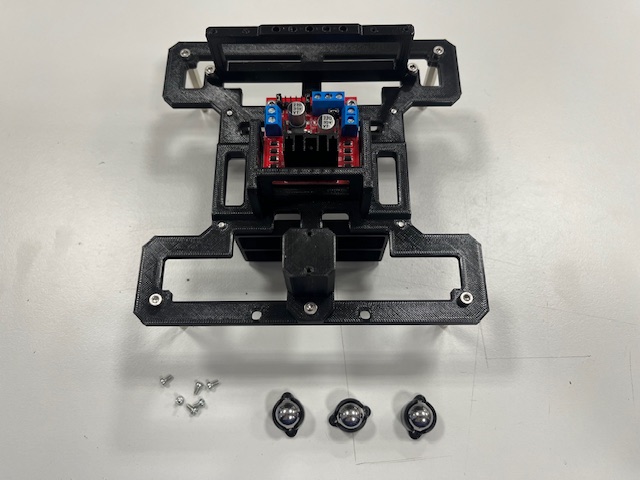
- Screw M3x6 (4x)
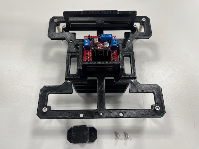
- Front leg
- Screw M3x6 (2x)
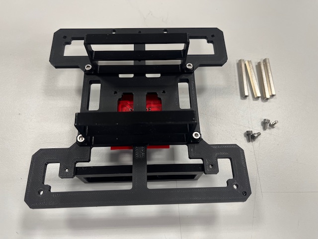
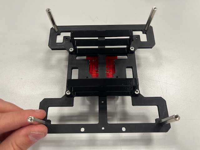
- Standoff (4x)
- Screw M3x6 (4x)
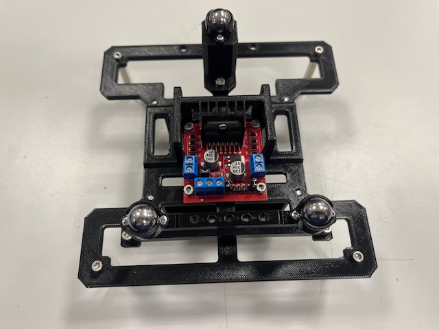
- Roller caster (3x)
- Screw M2x4 (6x)
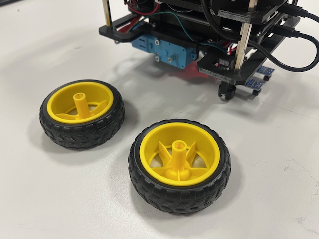
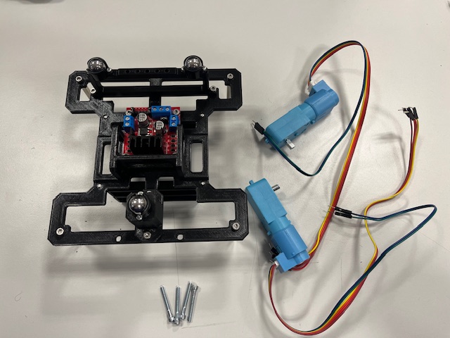
- Motor with 6-wire cable (2x)
- Screw M3x25
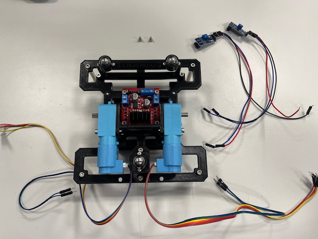
- Line sensor with 3 wires (2x)
- vcc (red)
- gnd (black)
- signal (blue)
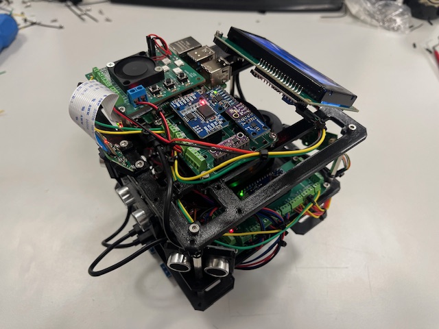
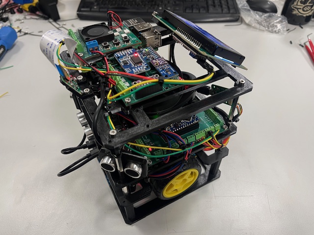
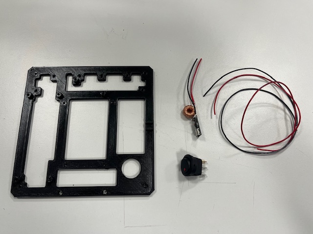
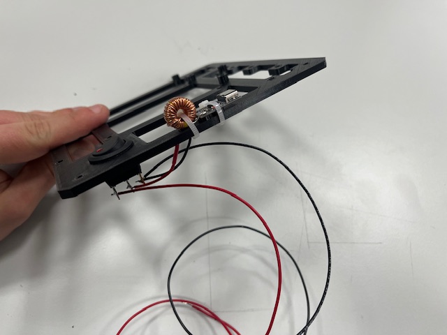
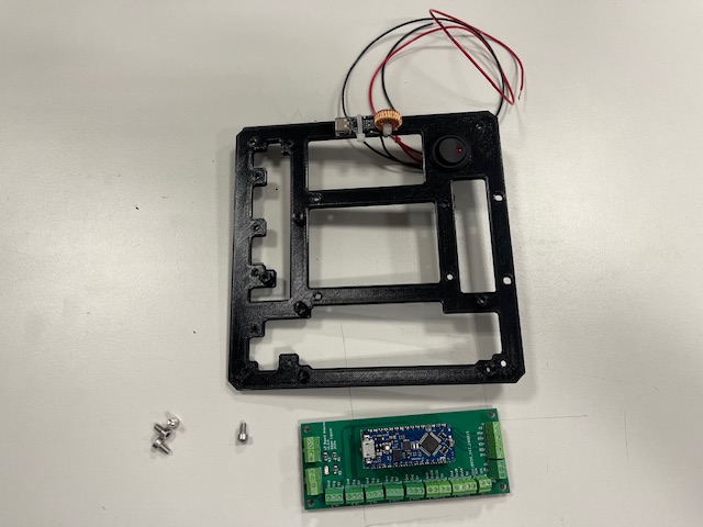
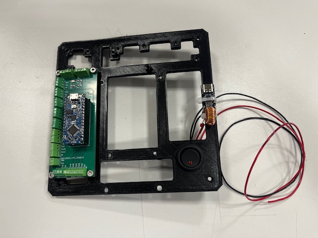
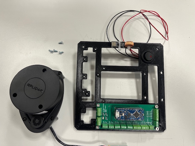
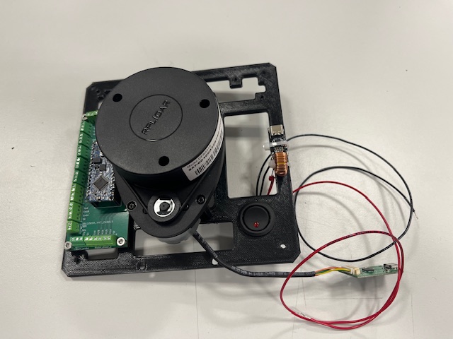
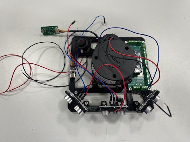
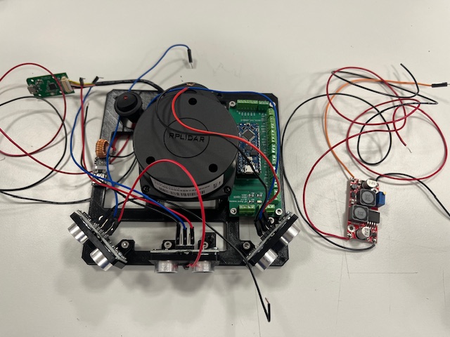
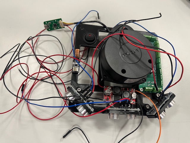
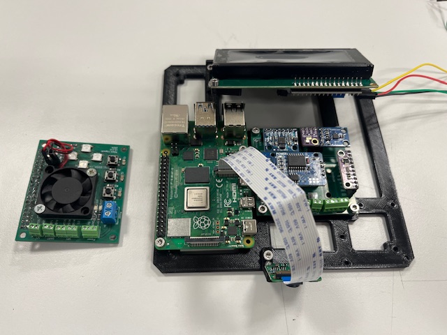
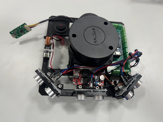
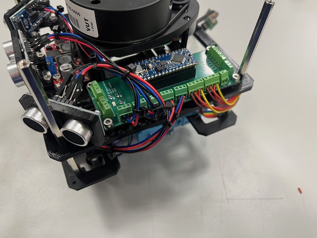
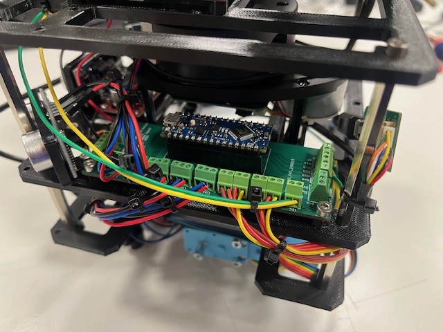
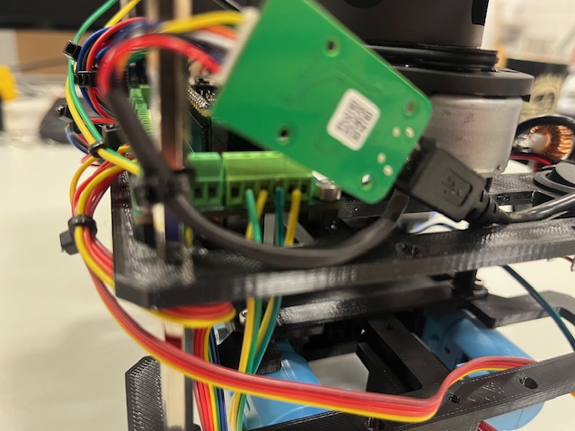
- Middle part
- Switch
- USB power delivery module
- Wires (red & black)
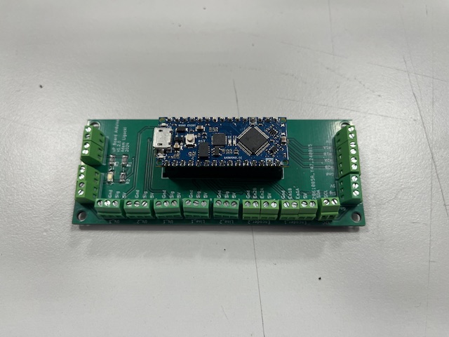
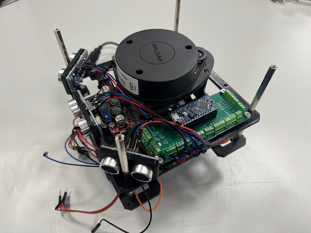
- Arduino board
- Screw M3x6 (4x)
- LiDAR with UART to USB converter and 4 screws
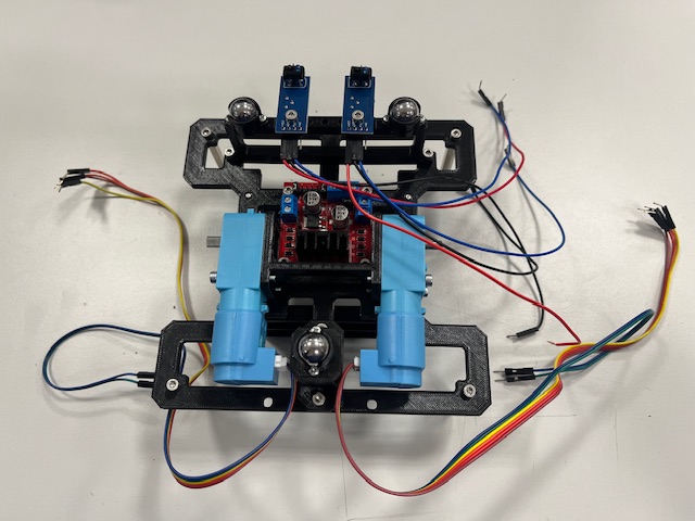
- Ultrasound sensor
- 3 wires
- vcc (red)
- gnd (black)
- signal (blue)
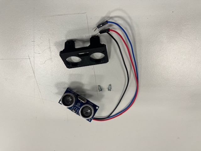
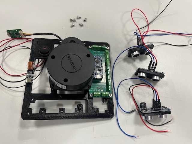
- Ultrasound module (3x)
- Screw M3x6 (6x)
- DC/DC stepup
- Screw M3x6 (2x)
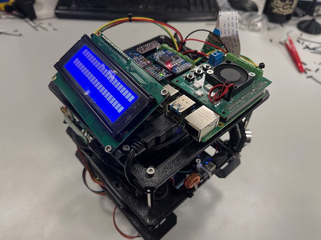
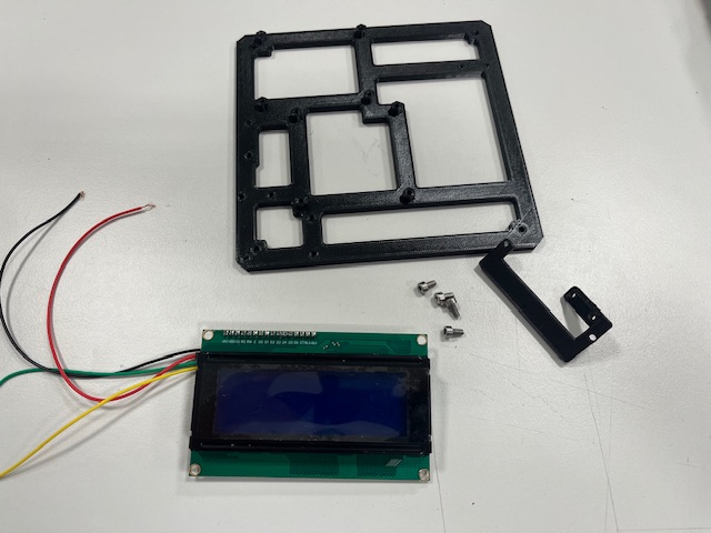
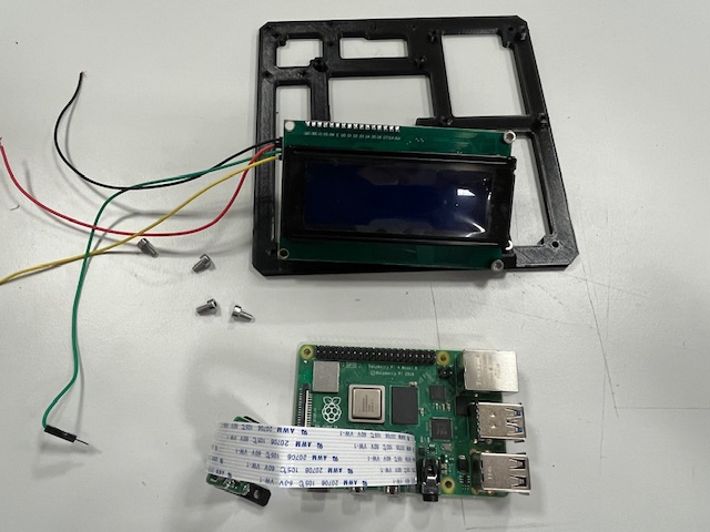
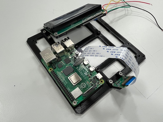
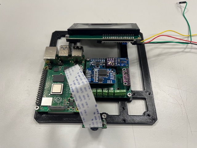
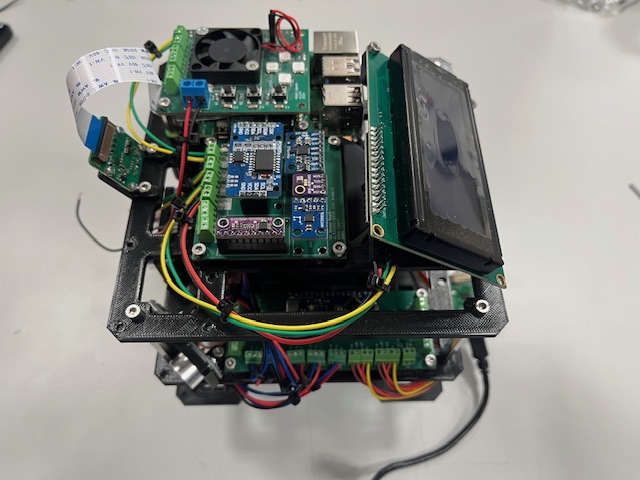
- Top Part
- LCD mount
- LCD
- Wires
- vcc (red)
- gnd (black)
- sda (green)
- scl (yellow)
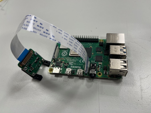
- Raspberry Pi 4
- RPi camera v2
- Camera mount
- 4x screw M2x3

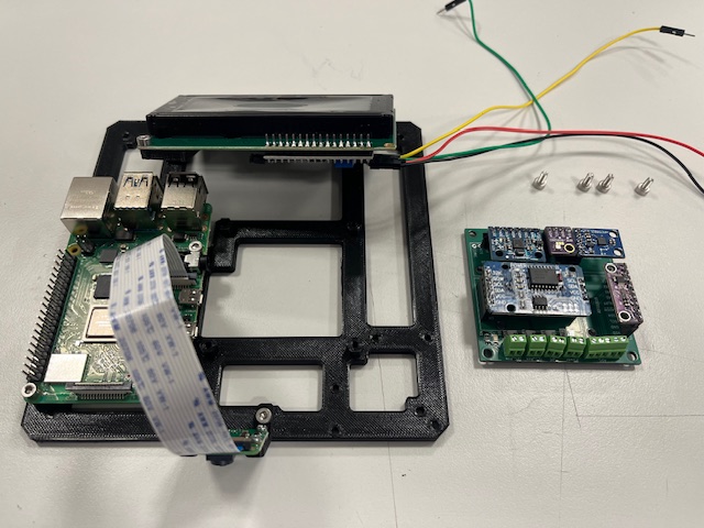
- Sensor board
- IMU
- ADC
- RTC
- Magnetometer
- Barometer

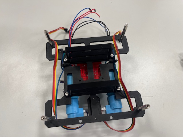
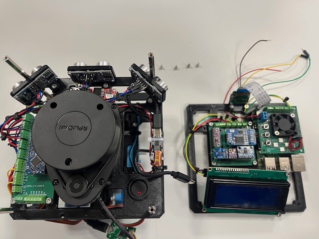
- Bottom module
- Mid module
- Standoff (4x)
- Left motor -> encoder 1
- Right motor -> encoder 2
- Left US -> us_1
- Center US -> us_2
- Right US -> us_3
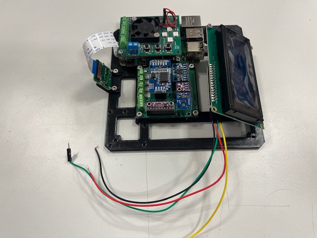
- Top module
- Screw M3x4 (4s)
- Wires (RPi power -> Arduino Board)
- Left motor
- M1A -> N1 (yellow)
- M1B -> N2 (green)
- Right motor
- M2A -> N3 (yellow)
- M2B -> N4 (green)
- vcc 5V (red)
- gnd (black)
- sda (gree)
- scl (yellow)